Midiboy Assembly Instructions
Welcome to the Midiboy assembly instructions! Here you will find all the information and steps required to solder and assemble your own Midiboy.
First go through the contents of the Kit and check if you have all the necessary tools (listed below) at your disposal.
Kit Parts List
| Image | Description | Qty | PCB Side | Position | Polarized* |
|---|---|---|---|---|---|
 |
Main PCB | 1 | - | - | - |
 |
Battery PCB | 1 | - | - | - |
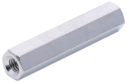 |
Metal standoff 25mm | 4 | - | - | - |
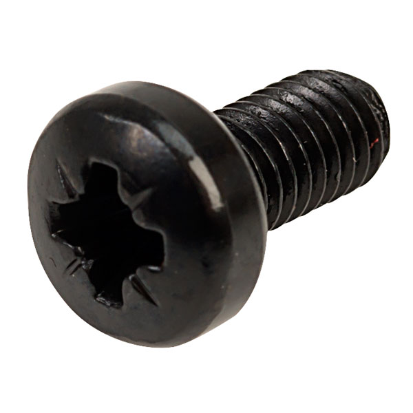 |
Bolt M3 | 8 | - | - | - |
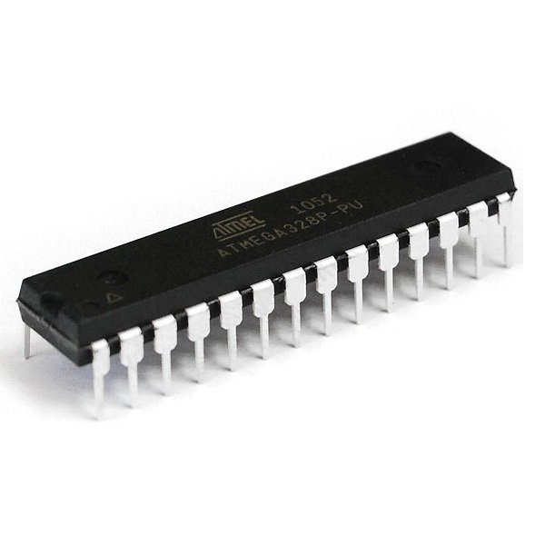 |
Atmega328P | 1 | Main PCB Bottom | ATMEGA328 | Yes |
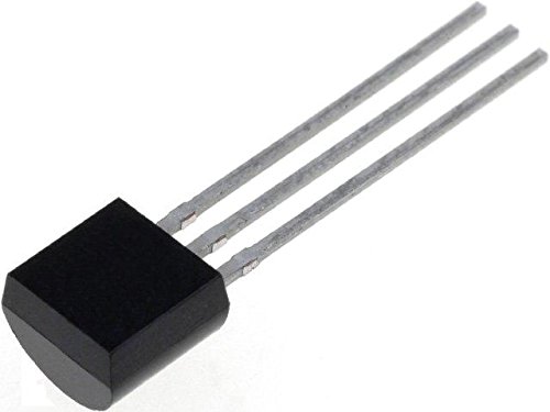 |
TS2950CT-5.0 voltage regulator | 1 | Main PCB Bottom | VREG | Yes |
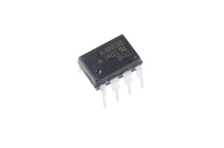 |
6N138 Optocoupler | 1 | Main PCB Bottom | OK1 | Yes |
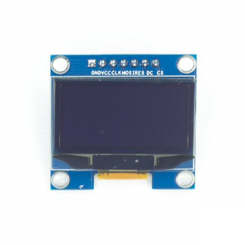 |
OLED Display 1.3" | 1 | Main PCB Top | OLED | Yes |
 |
Male header pin | 4 | Main PCB Top | P1, P2, P3, P4 | - |
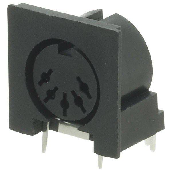 |
DIN-5 MIDI port | 2 | Main PCB Bottom | MIDI_IN, MIDI_OUT | Yes |
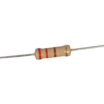 |
220 ohm resistor | 5 | Main PCB Bottom | R1, R3, R5, R9, R10 | - |
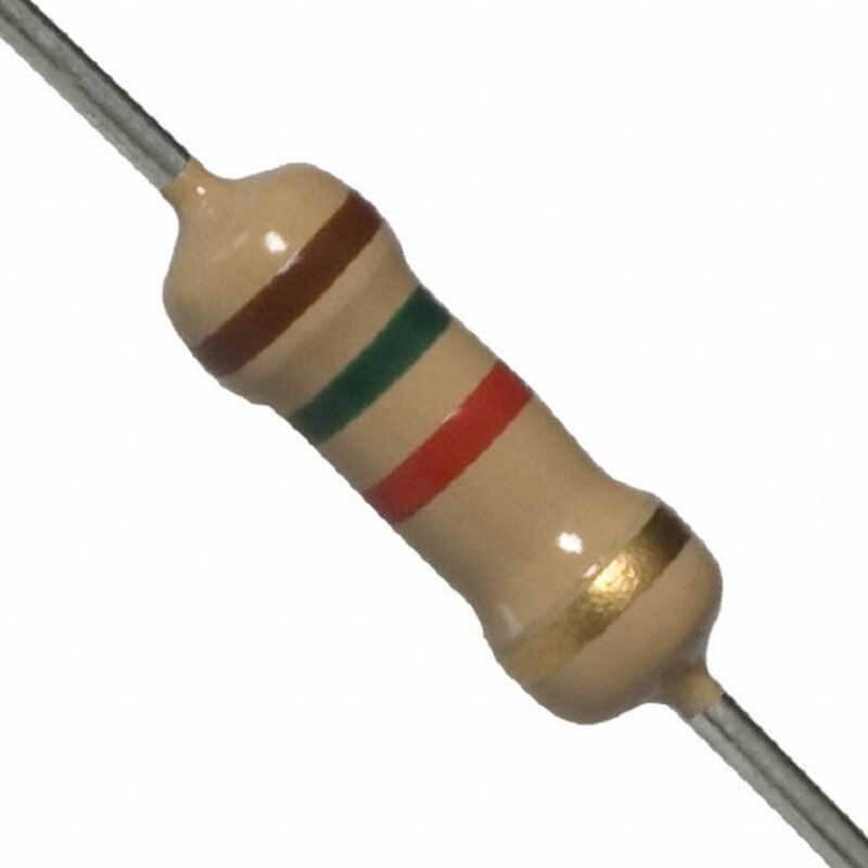 |
1.5k ohm resistor | 3 | Main PCB Bottom | R2, R4, R8 | - |
 |
68 ohm resistor | 2 | Main PCB Bottom | R6, R7 | - |
 |
1N5817 diode | 2 | Main PCB Bottom | D1, D2 | Yes |
 |
Zener diode / 1N4729 | 2 | Main PCB Bottom | D3, D4 | Yes |
 |
1N4148 diode | 1 | Main PCB Bottom | D5 | Yes |
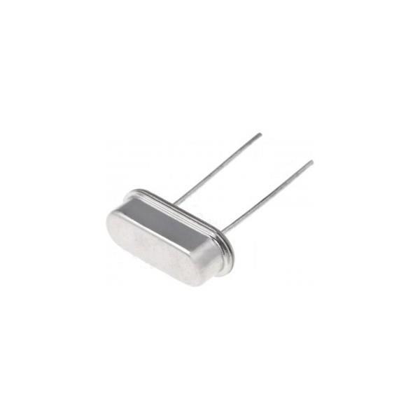 |
20MHz crystal | 1 | Main PCB Bottom | Q1 | - |
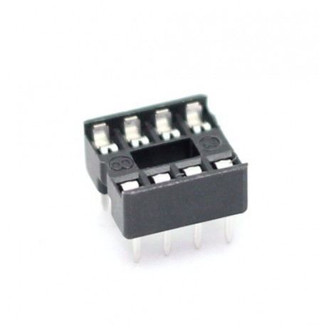 |
DIP8 socket | 1 | Main PCB Bottom | OK1 | Yes |
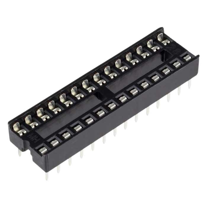 |
DIP28 socket | 1 | Main PCB Bottom | ATMEGA328 | Yes |
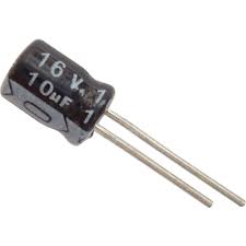 |
10µF electrolytic capacitor | 1 | Main PCB Bottom | C5 | Yes |
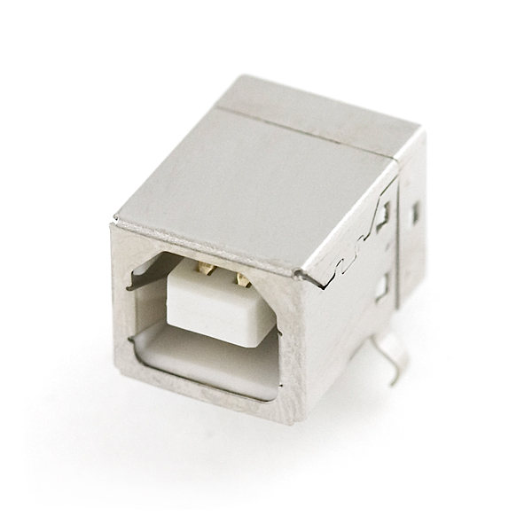 |
USB connector | 1 | Main PCB Bottom | USB | Yes |
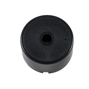 |
Loudspeaker | 1 | Main PCB Bottom | SPK | - |
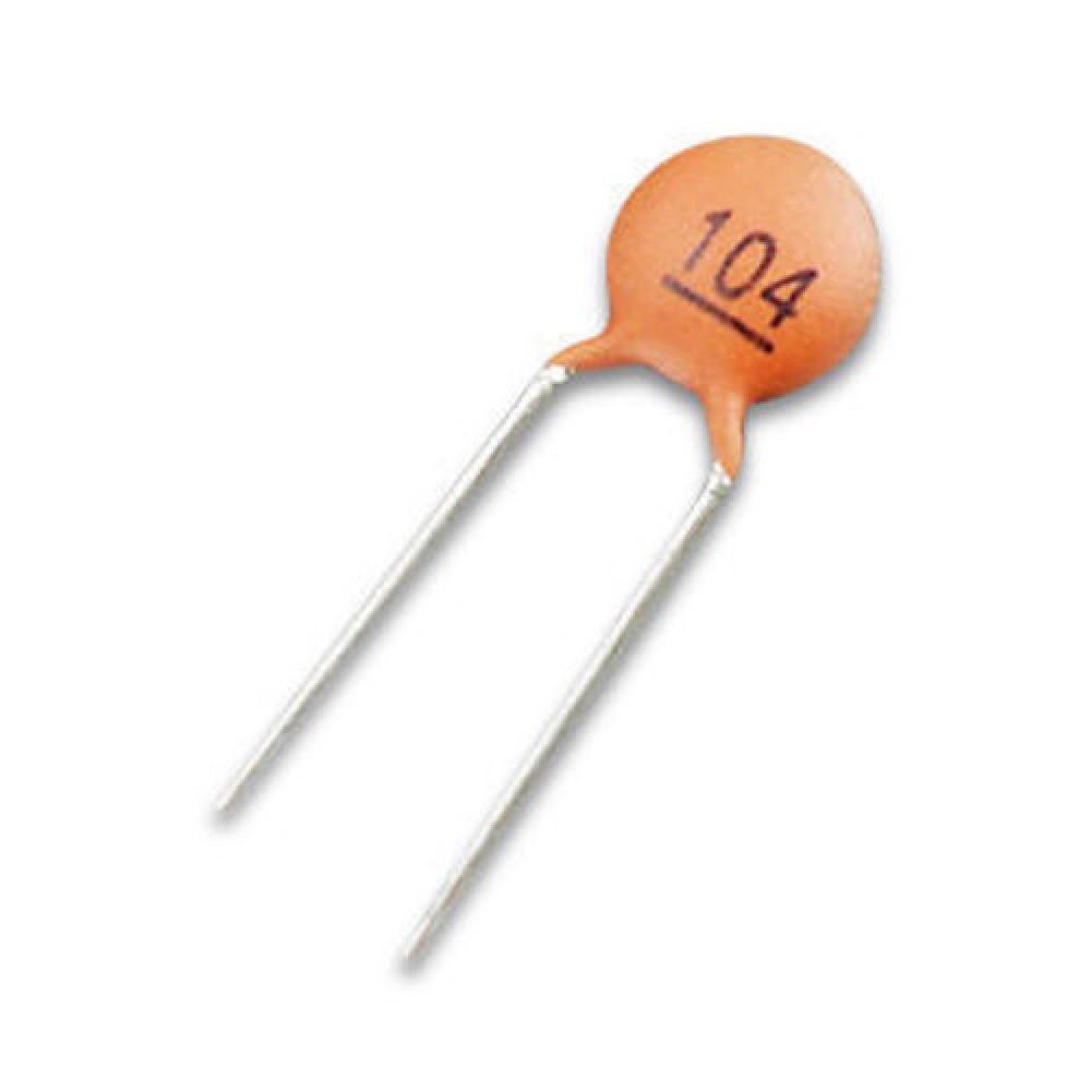 |
100nF ceramic capacitor | 2 | Main PCB Bottom | C3, C4 | - |
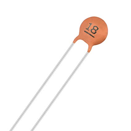 |
18pF ceramic capacitor | 2 | Main PCB Bottom | C1, C2 | - |
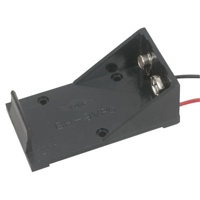 |
9V battery holder | 1 | Battery PCB Top | - | Yes |
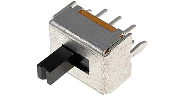 |
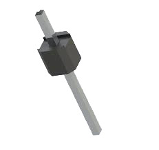
Power switch | 1 | Main PCB Top | S1 | - |
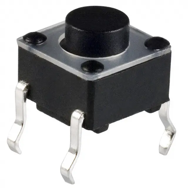 |
Push button | 6 | Main PCB Top | S2, S3, S4, S5, S6, S7 | - |
* Polarity indicates whether a circuit component is symmetric or not. A non-polarized component, a part without polarity, can be connected in any direction and still function the way it's supposed to. A part with polarity can only be connected to a circuit in only one direction. If a polarized component was connected to a circuit incorrectly, at best it won't work. At worst, component will smoke, spark, and be irreversibly damaged.
Tools Needed
Must Haves
Below are the tools and equipment that are required for the assembly of Midiboy and they are not included in the kit.
| Image | Description |
|---|---|
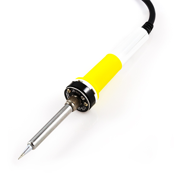 |
Any entry level soldering iron that you might find at your garage or local hardware store. Recommended power is ~30W. |
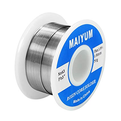 |
For soldering, you need solder (obviously). The easiest type to work with is 60/40 lead/tin. We recommended to use solder with rosin core. |
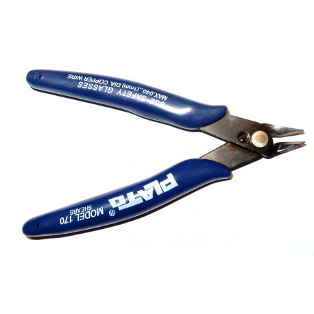 |
Cutting pliers are absolutely necessary when it comes to soldering. It is useful to trim the leads of your components or wires after soldering. A mini diagonal cutting pliers is perfect for this task. |
 |
You will need a 9V battery to power your Midiboy. Due to shipping restrictions the battery isn’t included in the kit. |
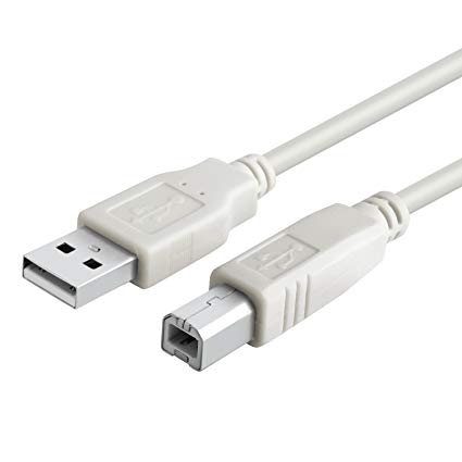 |
Later on you will need a USB-B cable to connect Midiboy to your computer. |
Optional
Extra tools that might come in handy.
| Image | Description |
|---|---|
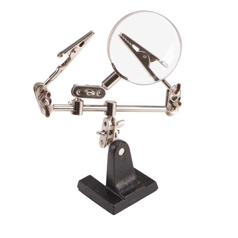 |
A helping hand holds your components together while you solder, leaving your hands free to perform your work. Helping hands come in all sorts of models with different accessories and features. And a magnifying glass can be useful to check the joints after soldering. |
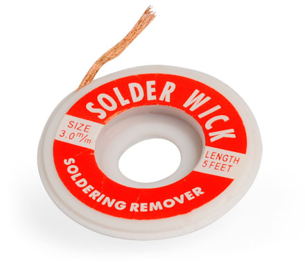 |
Solder wick soaks up molten solder, so it is really useful to clean the excess of solder during your soldering work or rework. |
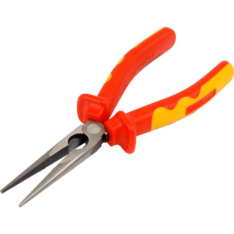 |
Long-nose pliers can be very useful in electronics work, e.g. bending component leads to fit a PCB, straightening component leads that have been bent or holding components when soldering. |
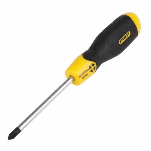 |
A regular Phillips-head screwdriver with a shaft diameter of 3mm or smaller is sufficient. You’ll need this one to fasten the standoffs to PCBs, but usually this task can be achieved by using fingers. |
Before You Start
If you haven’t soldered before, here are some videos to get you going:
- https://youtu.be/QKbJxytERvg
- https://youtu.be/f95i88OSWB4
- https://youtu.be/J5Sb21qbpEQ
- https://youtu.be/fYz5nIHH0iY
Generally, the kit should be assembled starting from lowest height parts, finishing with the tallest ones. The recommended order is described below. All of the parts must be inserted from the side that contains the part outline.
If some of the instructions are not clear, don’t hesitate to ask us or the Midiboy community on how to proceed. Best place to do so is our community forum - https://community.blokas.io/.
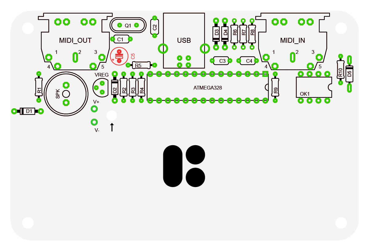
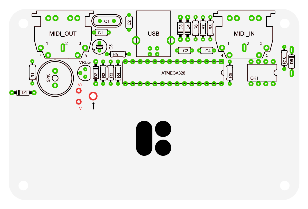
Assembling Main PCB Bottom Side
Resistors and Diodes
First you should start from the lowest height parts, so go ahead and insert all of the resistors to their designated locations, bend their wires slightly near the PCB, so they don’t fall out unintentionally. Don’t solder them yet, we will be adding in the diodes too, since they are almost the same height.
Insert the 220 ohm resistors in R1, R3, R5, R9, R10 positions. The 220 ohm resistors are marked with RED, RED, BROWN and GOLD/SILVER lines.
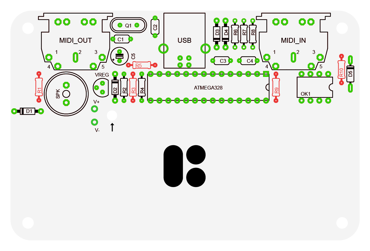
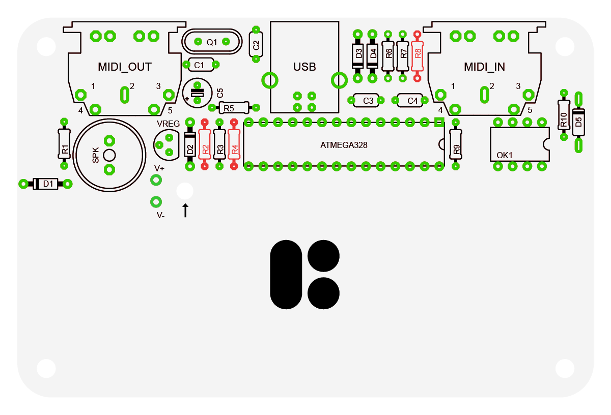
Insert the 1.5k ohm resistors in R2, R4, R8 positions. The 1.5k ohm resistors are marked with BROWN, GREEN, RED and GOLD/SILVER lines.
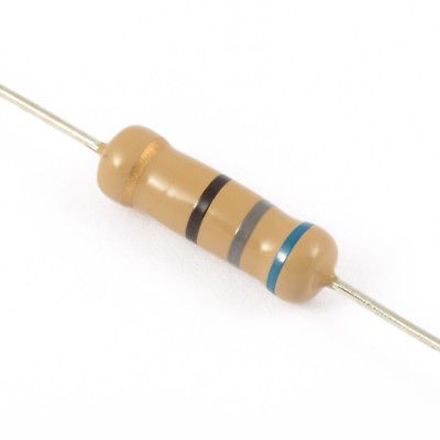
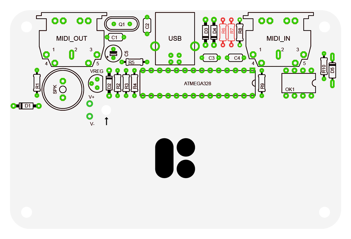
Insert the 68 ohm resistors in R6, R7 positions. The 68 ohm resistors are marked with BLUE, GREY, BLACK and GOLD/SILVER lines.
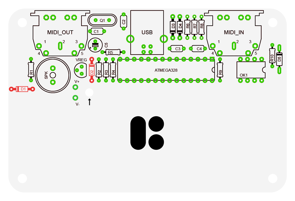
Moving on to the diodes. The diodes have a line indicating their polarity and must be inserted the right way around, the line must be on the side indicated on the PCB outline.
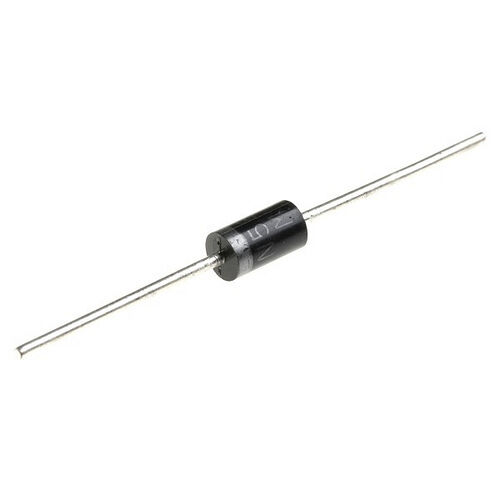
Insert the 1N5817 diodes in D1, D2 positions. The 1N5817 comes in a black body. The GREY line indicates the NEGATIVE lead.
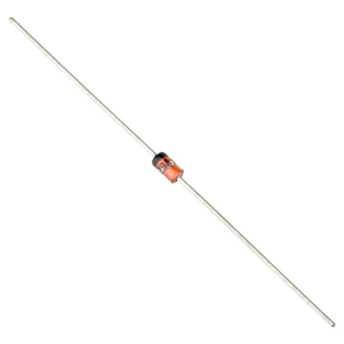
Insert the 1N4729 diodes in D3, D4 positions. The 1N4729 comes in an orange-ish body. The BLACK line indicates the NEGATIVE lead. Bigger compared to 1N4148 diode.
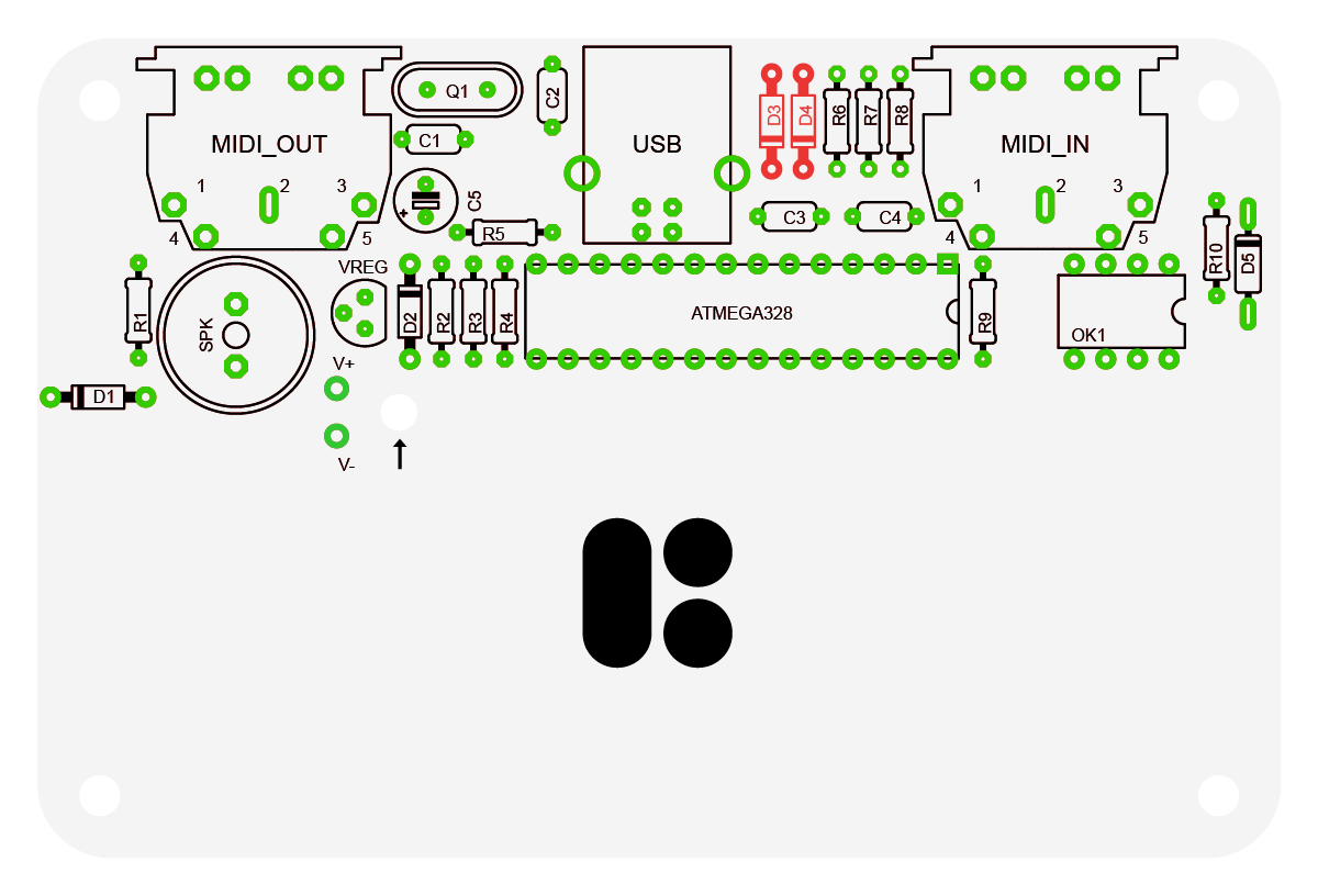
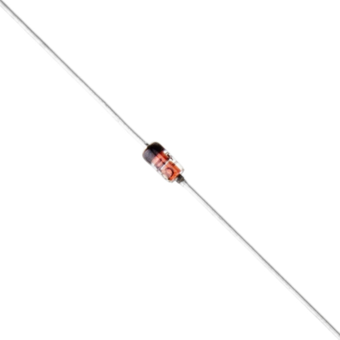
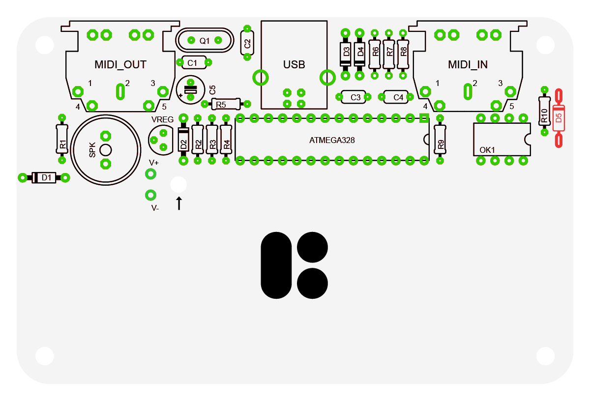
Insert the 1N4148 diode in D5 position. The 1N4148 comes in an orange-ish body. The BLACK line indicates the NEGATIVE lead. Smaller compared to 1N4729 diode.
Once the resistors and the diodes are in place, solder each joint. We recommend first doing one joint of each component, so the parts are firmly in place, then take a look around the other side of the board if the components are close to the board and look properly placed. If not, then you may re-heat that one solder joint, and adjust the part while the solder is hot and liquid. Don’t keep it hot for too long, try not to exceed 5-7 seconds, if you do, just make a short pause to allow the components to cool off. Be careful not to overheat the part and not to burn your fingers (use your pliers or tweezers to tweak the part).
Then do the rest of the solder joints of the components. Cut the wires using your wire cutter pliers.
Crystal
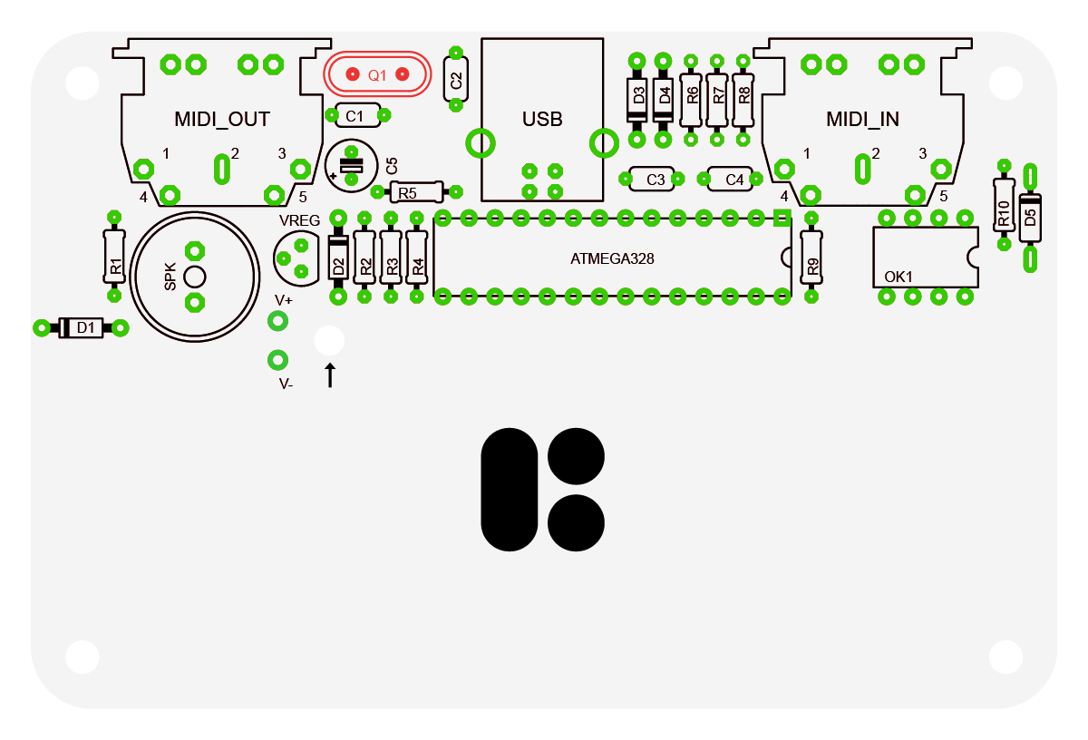
This one’s easy, insert the 20MHz crystal into Q1 slot, solder it and cut the wires.
DIP Sockets
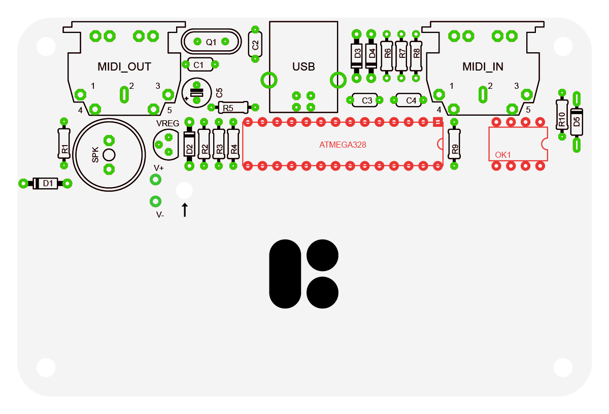
Insert the DIP sockets into ATMEGA328 and OK1, note that the sockets have a small notch on one of the short sides, you should align it with the notch marked on the PCB. As the part will block most of the silkscreen, it will help determining the way the actual integrated circuit (IC) must be inserted.
Capacitors
Now is the time to solder the capacitors. Begin by soldering the 10µF electrolytic capacitor in C5 position. The electrolytic capacitor must be inserted so that the stripe (the NEGATIVE pin) is on the same side as the black-filled rectangle on the PCB. To double check, the POSITIVE lead of the capacitor is longer and is marked with a little plus sign on the PCB.
Insert the 100nF ceramic capacitors in C3, C4 positions. They are marked with a “104” label and are a bit bigger compared to 18pF ones. The ceramic capacitors can go in any direction.
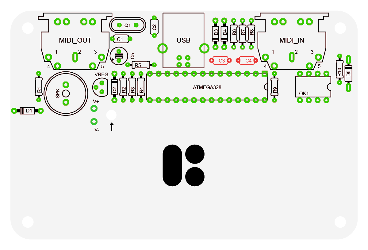
Insert the 18pF ceramic capacitors in C1, C2 positions. They are marked with a “18” label and are a bit smaller compared to 100nF ones. These also can go in any direction.

Once the 100nF and 18pF ceramic capacitors are in place, solder them and cut the wires using your wire cutter pliers.
Voltage Regulator
Bend the middle pin of the TS2950CT regulator slightly back and insert the component into the 3 holes of VREG. Make sure to insert it with the flat side on the same side as shown on the PCB outline for the part. The part should remain slightly above the PCB, don’t try to force it down too much.

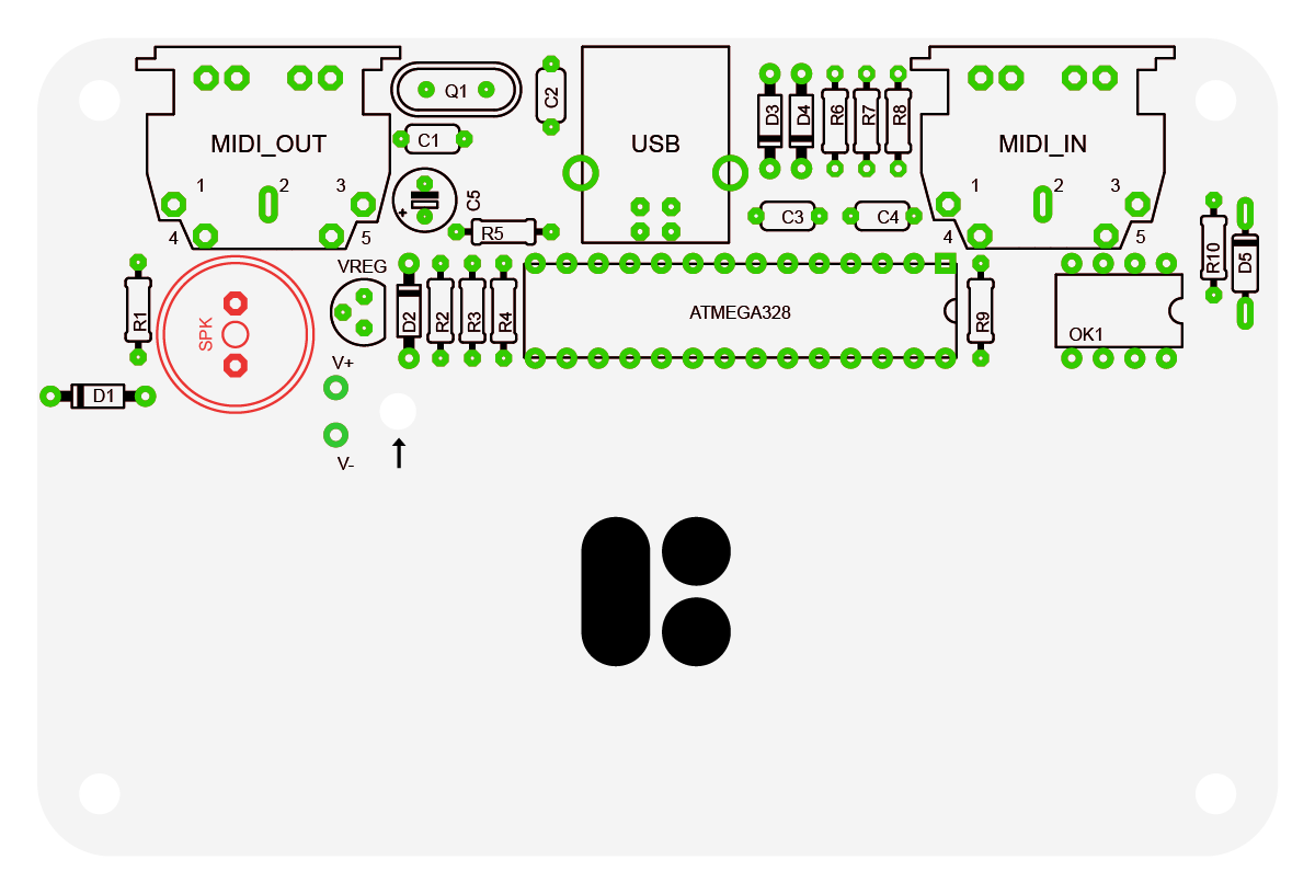
Loudspeaker
Insert the speaker into its location and solder it. Either component direction is fine.
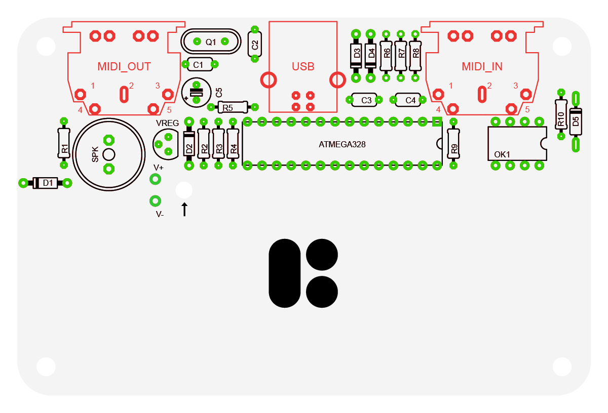
USB and MIDI Ports
Insert and solder the ports. Again, you may want to solder a single pin of each component first and ensure the component is flush with the board. If it’s not, you can reheat the pin and adjust the component. Then go ahead and finish the rest of the joints.
Assembling Main PCB Top Side
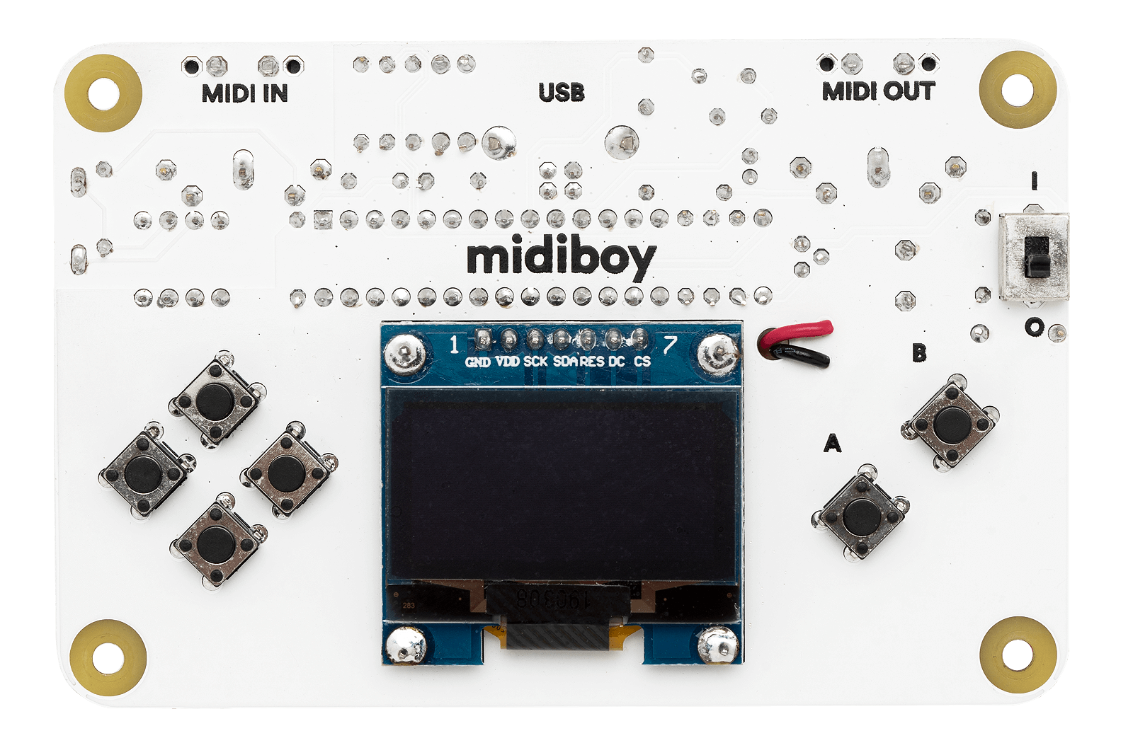
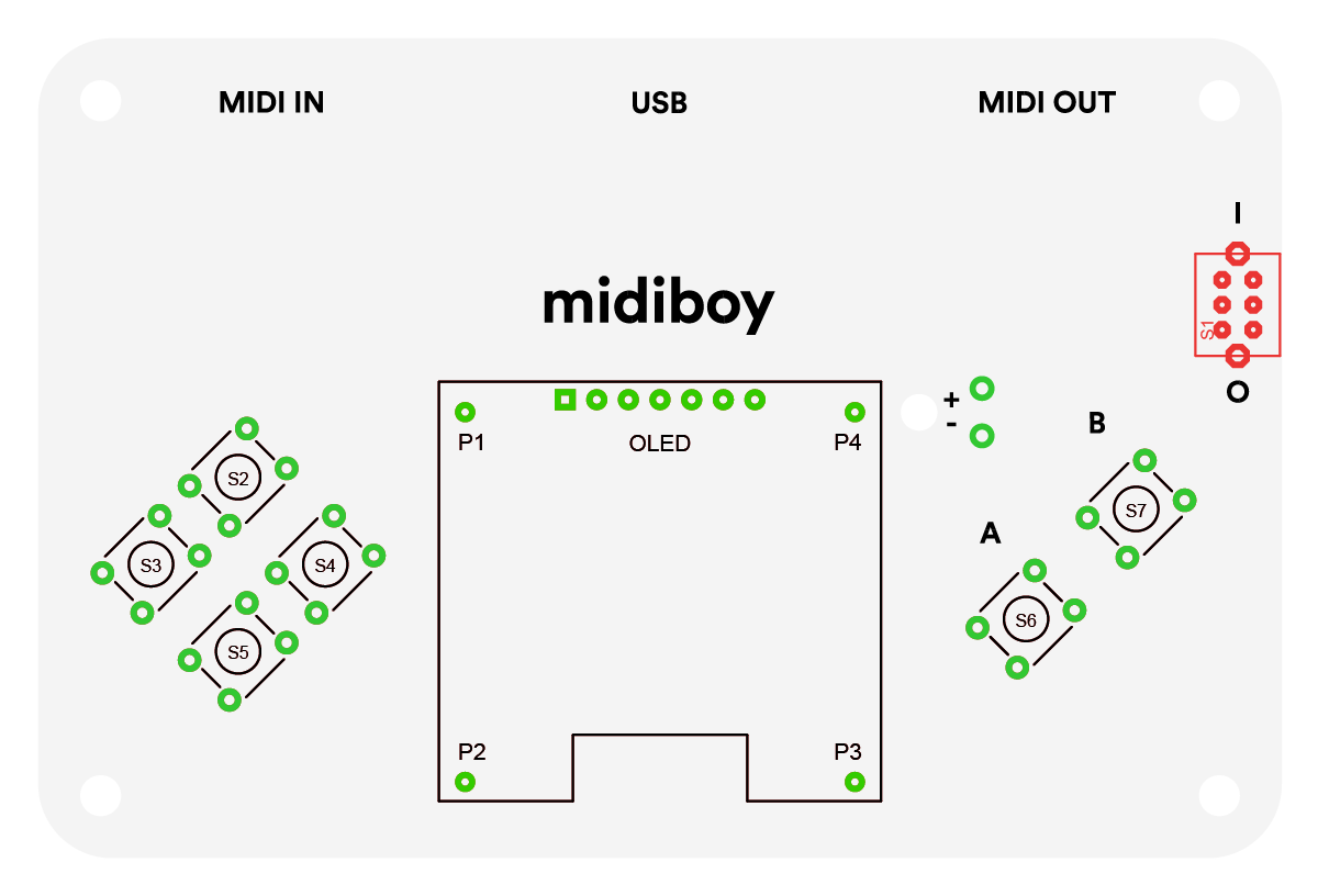
Display
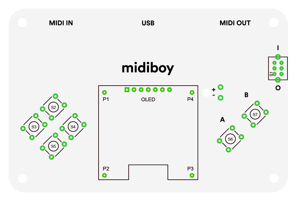
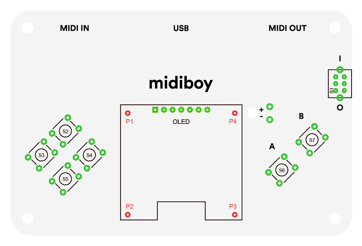
The display is mounted to the PCB using the 4 male header pins on each corner of the display (P1, P2, P3, P4). Place all of the pins in the corner holes on the PCB, with the longer part of the pin going through into the PCB hole.
Then put the display on top of them and through its own line of holes.
The corner pins may appear that they are not straight at this stage, but you should be able to make sure they are lined up during soldering.
Don’t take the screen protector off until you are done soldering the display - the resin from your solder may spill on the screen during soldering nearby.
First solder either the leftmost (1, square one) or the rightmost (7) pin of the display, so it is held in place. Then go on soldering one of the corner pins to the display.
The corner display holes are quite big, so make sure to use enough solder to fill the entire hole diameter, and from time to time move your soldering iron to a different position to spread the heat.
Make sure to heat the ring on the display and the pin itself simultaneously, so the solder attaches well to both parts. You may carefully pressure the display down using your fingers at a safe distance to get the pin positioned correctly,
as well as tweak it slightly with your soldering iron (don’t use excessive force, also don’t keep it all heated up for too long, if needed, make a short pause so that the parts cool off). Once you’re happy with the pin, solder it down to the main PCB.
Continue the above for the remaining 3 corner pins, starting from the one which is in diagonal location to the freshly soldered one.
Then go on to solder the rest of the display pins.
Cut the pins on the bottom side of the PCB using the wire cutter pliers. These pins are likely to fly off while cutting, so don't face the board directly. We recommend cutting the pins while directing them towards your table surface.
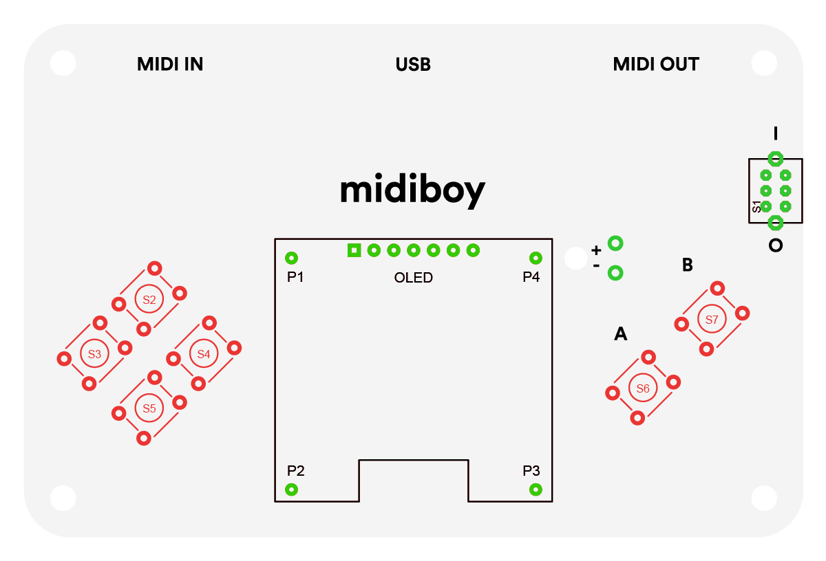
Push Buttons
Insert the tactile buttons into their positions (S2, S3, S4, S5, S6, S7) and solder them. They can go in in any direction.
Power Switch
Insert the power switch (S1) and solder it down. It can be placed in any direction.
Inserting ICs
Insert the ATmega328P and the 6N138 Optocoupler into the ATMEGA328 and OK1 sockets respectively. They must be inserted the right way. The direction of the IC parts is indicated by a notch on one side and/or a small circle at one of the corners of the part. The part should be inserted so that the indicator matches the notch of the part outline on the PCB.
The pins of the IC may initially be angled too widely to fit into the IC socket. They should be bent a bit by hand, so they can fit snugly into the socket. It’s best to bend the entire line of pins at the same time. This can be achieved using long nose pliers, or simply a flat surface. You may hold the part on its side down to the table, so the entire line of pins is touching the surface, and then rotate it, so that the pins bend inwards. Repeat the same for the line of pins on the opposite side.
Testing
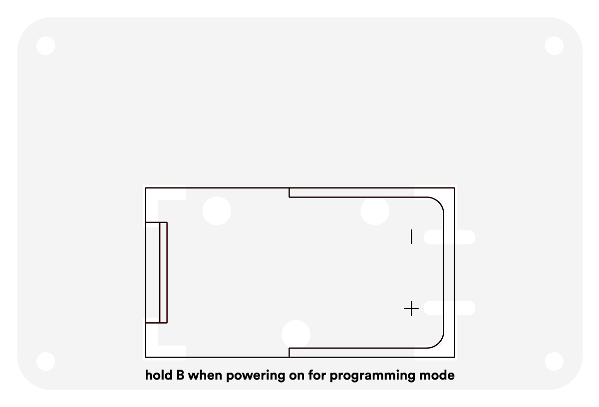
Now that we have all of the main components in place, and as Midiboy can be USB powered, we can make a quick test to see if it works. Plug in the USB cable to a computer and flip the power switch to the ON position. Initially there’s no software installed apart from the Bootloader. The display should show the Blokas logo, and the computer should recognize the device as a COM port.
If there’s something wrong, look at the Troubleshooting section at the last step of this guide.
Assembling Battery Holder PCB
Battery Holder
Before gluing the battery holder to the bottom PCB, let's wire it up to the main pcb.
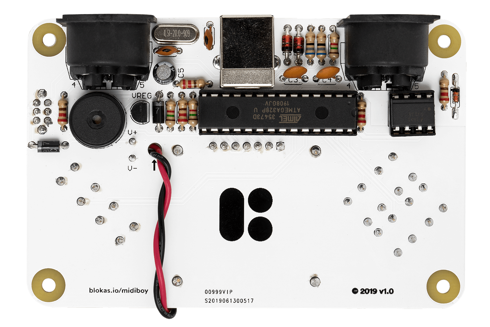
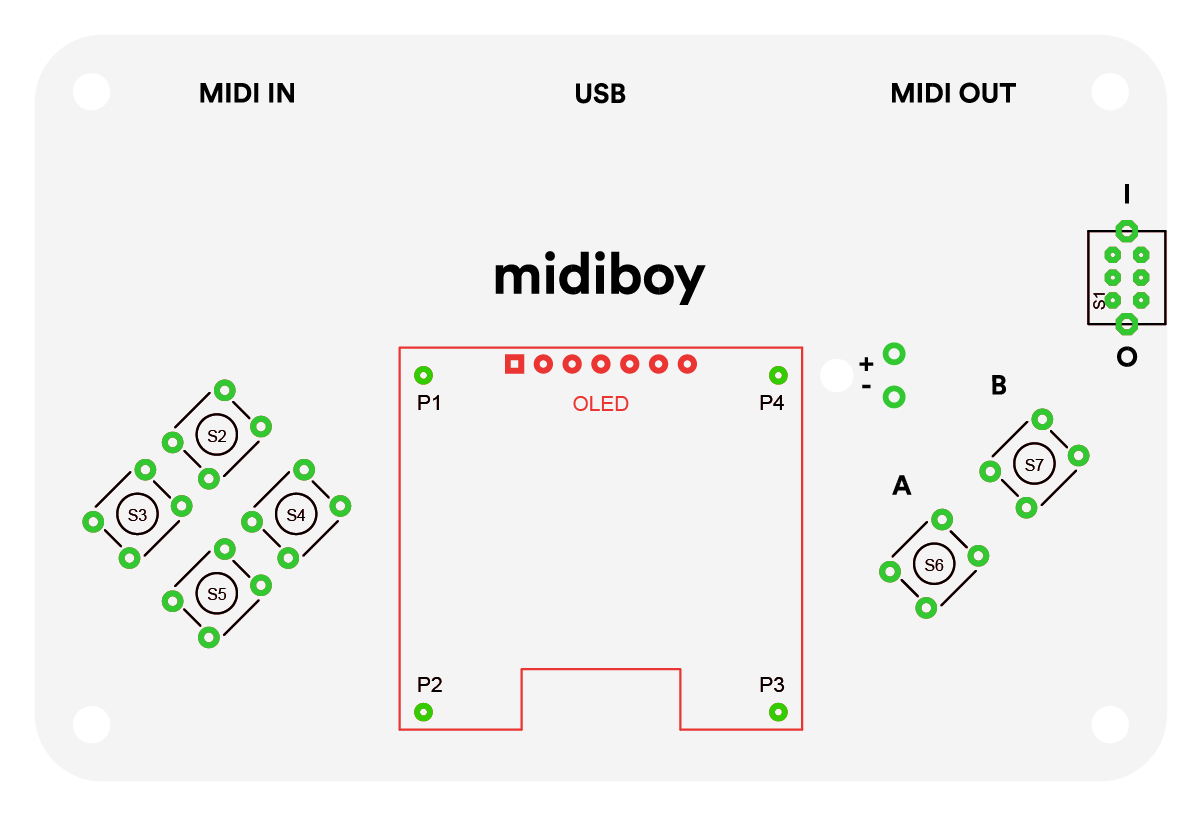
First pull both of the black and white wires through the hole near the display marked with an arrow, inserting the wires from the bottom side going to the top side.
Pull as much wire through as possible, but keep enough space to be able to solder the wires down. From the top side, insert the red wire into the hole marked with a + (V+ on the bottom side),
and the black wire into the hole marked with a - (V- on the bottom side), and solder them.
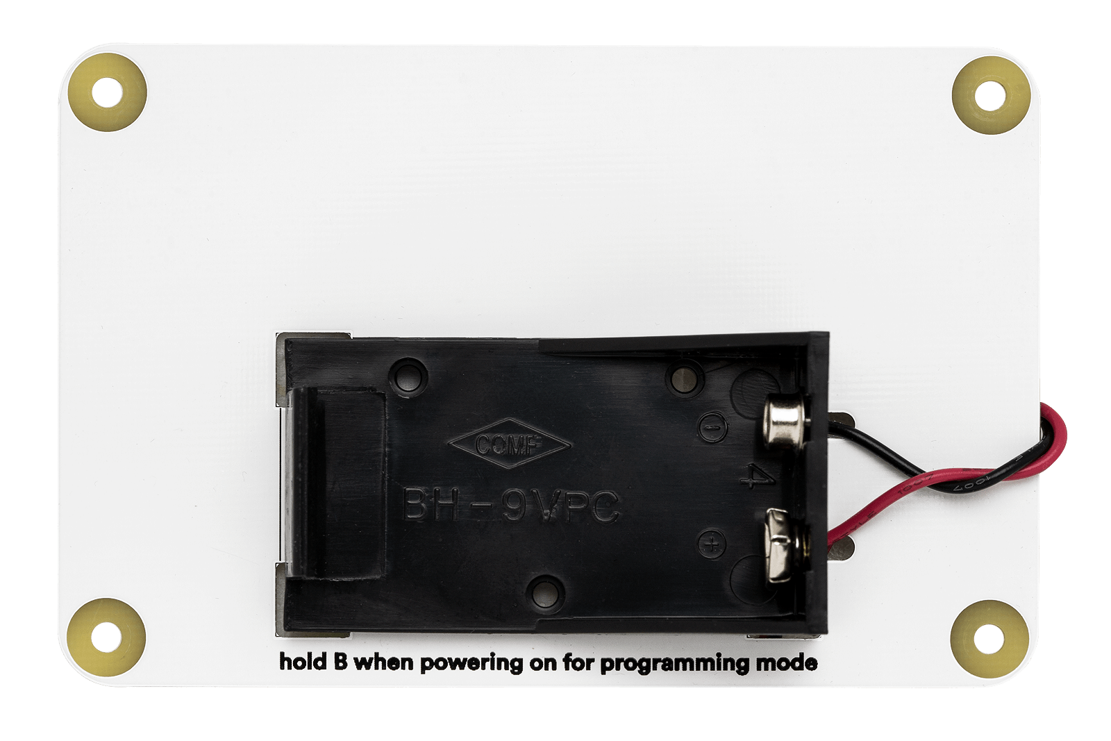
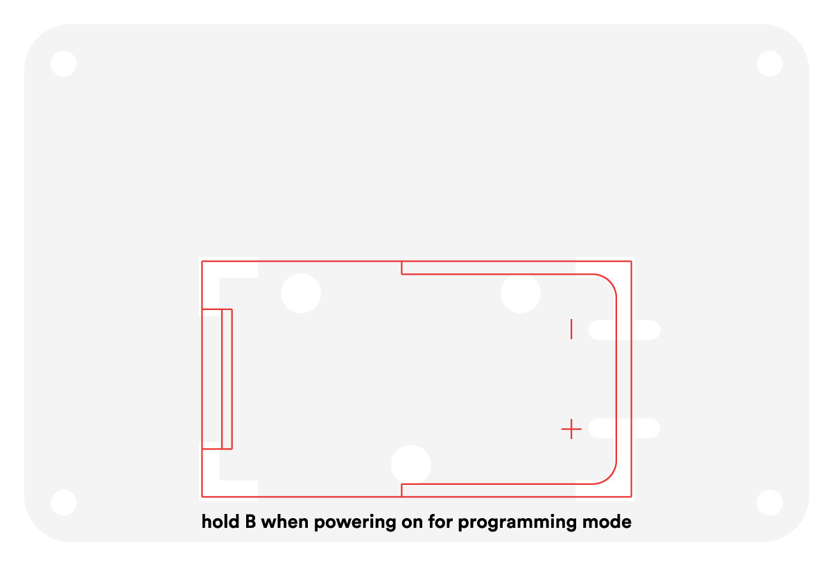
Then peel the protective layer from the double sided tape under the battery holder off and glue the holder onto the battery holder PCB.
Quick Test
Insert a 9V battery into the holder in the right polarity and try powering the device up. If all is well, you should see the Blokas logo on the display. If not, look at the Troubleshooting section down below.
Mounting It All Together
First let’s make sure the battery holder wires will not get in our way - hold the battery holder PCB in one hand, the main PCB in the other. Rotate the main PCB a couple of times, so that the battery wires are contained entirely within the bounds if the both boards would be stacked together.
Then simply fasten the boards together using the 8 screws and the 4 extenders.
Done! Thank you!
Now you should go on and upload some software!
Troubleshooting
If something ain’t right, here’s a troubleshooting list to get you started in determining the cause:
- Are all the polarized parts inserted the right way around?
- Are the components in their right locations?
- Are all of the solder joints making good contact?
- Is the ATmega328P inserted well?