Audio Specifications
Pisound is equipped with 192kHz 24-bit Stereo Input and Output. The legendary Burr-Brown Op-Amps, ADC and DAC chips are implemented in this little board to exhibit clean signal amplification and conversion between digital and analog realms. Though these chips themselves have a good power supply rejection ratio (PSRR), to ensure low-noise operation in the vicinity of an electrically noisy Raspberry Pi computer, any power line to the analog stuff is coupled via LDO’s which filters any digital interference out. This design enables Pisound to be graded as a high-fidelity audio device. For example a Hi-Fi device is expected to have the total harmonic distortion value (THD) less than 1% and the Pisound has less than 0.05%. That means that you can daisy-chain 20 Pisound boards and the chain would still be considered as a high-fidelity device!
| Parameter | Conditions | Value |
|---|---|---|
| Input/Output Coupling | - | AC and DC respectively |
| Input/Output Channels | - | 2 / 2 (Left and Right) |
| Input/Output Type | - | ¼" (6.35 mm) Stereo |
| Input/Output Resolution | - | 24bit |
| Sampling Frequency (Fs) | - | 48 kHz, 96 kHz, 192 kHz |
| Input/Output SNR@1kHz | G = 0 dB | 110 dB |
| Input Impedance | - | 100 kOhm || 2 pF |
| Input Gain (G) | - | 0 dB to +40 dB |
| Input Clip LED | - | Yes |
| Input Clip Voltage | G = 0 dB | 2.5 V (peak to peak) |
| Full Scale Output | Load impedance > 1 kOhm | 0V to 2.1 V (RMS) |
| Loopback Bandwidth (-3 dB) | G = 0 dB, Fs = 48 kHz | 7.5 Hz - 23 kHz |
| Loopback THD@1kHz | G = 0 dB, Fs = 48 kHz | < 0.045% |
| Loopback Latency | Fs = 192 kHz, RPi2, buffer size = 128 frames | 2.092 ms |
| Phantom Power | - | None |
Audio Input
There is one unbalanced stereo input accessible via ¼" (6.35 mm) jack slot on Pisound. The input stereo connector can also be used as two unbalanced mono channels. Audio inputs are AC coupled to a gain stage built using OPA4134 op-amps. Input resistance is 100 kOhm for each channel. The gain can be adjusted simultaneously for both the left and the right channels from 0 dB to +40 dB with an on-board potentiometer. The maximum audio signal level before clipping is 2.5 Vpp (at 0 dB gain). The range of the gain adjustment can be divided into two sections. The first section occurs at rotation between 0% and 80% and it is used to precisely adjust for the high-level signals (line out, headphone amp out, etc...). The tight section at the maximum rotation of the gain pot acts as a +20 dB switch for the low-level signals (guitar, microphone, etc.). When the signal clipping occurs in any channel, the red LED lights up and fades out after last clipped sample. Audio to digital conversion is carried out by PCM1804 converter. An on-board clock oscillator delivers a clock signal to the ADC, which divides it according to the selected sample rate. ADC acts as the master of I2S line. Pisound supports three sample rates: 48 kHz, 96 kHz and 192 kHz. A filter at the input stage of PCM1804 ensures good anti-aliasing
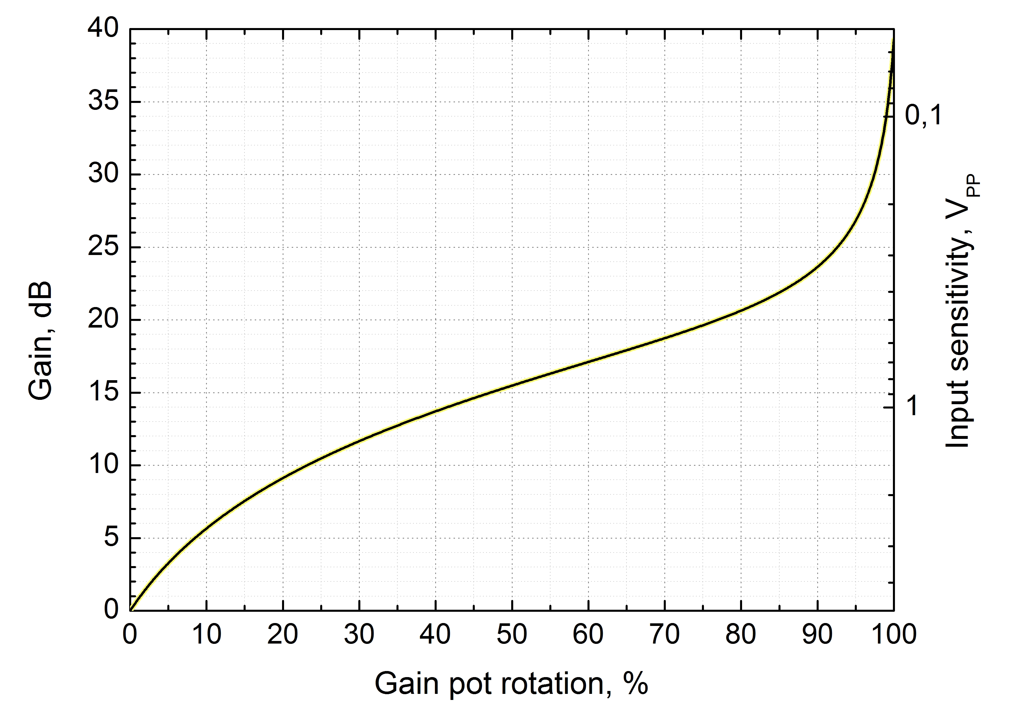 Gain and input sensitivity versus position of GAIN pot
6V Bias Solder Jumpers
There are two solder jumpers near the input port, one for each input channel. By default, the jumpers are unsoldered. If the solder jumper is soldered*, it enables the 6 V bias voltage with a 2.2 kOhm resistor for the input channel, and that allows connecting electret microphones.
| Solder Jumper State | Description |
|---|---|
| Unsoldered (default) | No bias voltage. For use with dynamic microphones, guitars, etc... |
| Soldered | Bias voltage enabled. For use with electret microphones. |
* Be careful when soldering. Any physical damage caused by improper soldering will void the warranty. Fortunately the solder jumpers are in an open area on the board.
Audio Output
Audio output is DC coupled and can be accessed via the female ¼" (6.35 mm) stereo jack connector. Output volume level can be adjusted with on-board potentiometer. Maximum output level is 2.1 Vrms when driving 1 kOhm load. Digital to audio conversion is done in PCM5102A converter which has both Signal-to-Noise ratio and dynamic range of 112 dB. The DAC acts as a slave on I2S line and the sampling rate is dictated by the ADC. An intelligent muting system is used to prevent pops and clicks when disconnecting power supply.
Audio Latency and Other Parameters
In digital audio equipment it takes time for the signal at input to be processed and delivered at output. This time is called audio latency. There's three parts to it. The first is the time required for the ADC to do the conversion and to send digital data to the processing unit. The second step is to process data and prepare it for the transfer to the DAC. And the final part is getting the data to the DAC and converting it to the analog signal. The most time consuming is the second part. Parts one and three often require no more than 1 ms depending on architecture of ADC and DAC, sample rate and in-built digital filters.
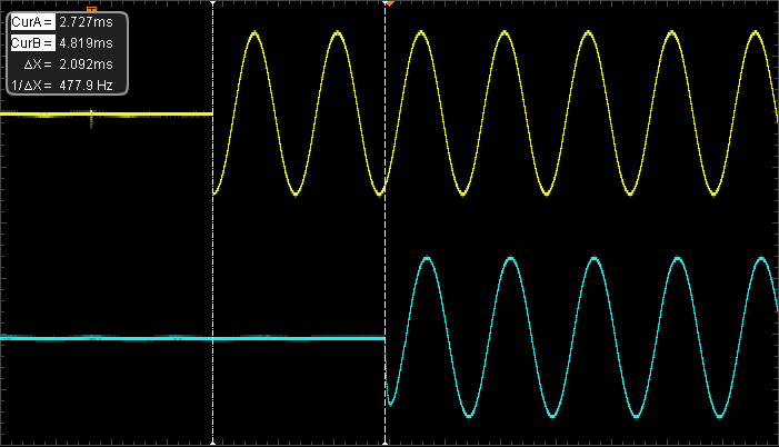
An oscillogram showing audio latency of 2.092 ms. Pisound and Raspberry Pi 2 working at sample rate of 192 kHz
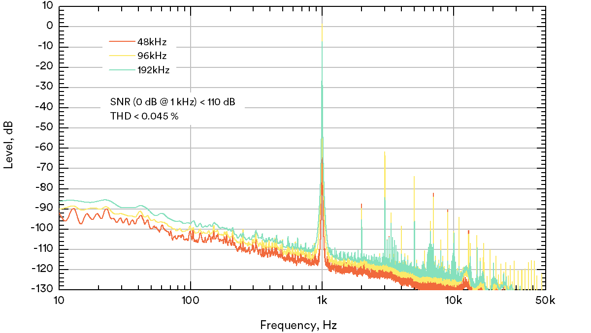 Figure 1 Response of the sine signal fed to loop-backed (digital→DAC→ADC→digital) Pisound showing the Signal-to-Noise Ratio (SNR) of 110 dB. Calculated Total Harmonic Distortion (THD) is less than 0.05%.
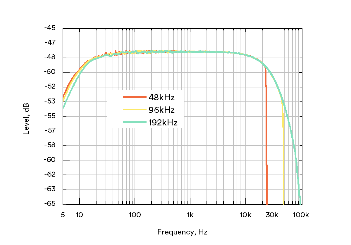 Figure 2 Frequency response of the white noise fed to loop-backed (digital→DAC→ADC→digital) Pisound showing the bandwidth (BW) of the device and how it is estimated.
Comments & Questions
For more tips & tricks join our community forums! 👋If you have any questions about the information on this page let us know below! 👇